FETA Probe
The newly created probe architecture is an extension of the original probe with the FETA acceleration module, which, with the appropriate use of the connection table, allows for the effective solution of other required functions: (i) collection of information on network flows, (ii) detection of security events using the Suricata IDS, and (iii) analysis of encrypted network communication. In order to be able to transfer the architecture to various acceleration cards, the newly designed probe is built on the NDK platform, which simultaneously ensures the reception of packets from the network and implements DMA for fast transfers over the PCI Express bus.
The architecture diagram is shown in Figure 1. After receiving the input packets from the network interface, they are stored in the packet FIFO memory and are simultaneously passed to the Packet Analyser component, which consists of two parts — Header Field Extractor (HFE) and Payload Analyser (PA). HFE analyzes packet headers and extracts important items such as MAC addresses, IP addresses, TCP/UDP ports, and the like. The PA unit processes packet data and calculates various functions on them, which can then be used for traffic analysis using classifiers created using machine learning. Examples of such functions include entropy calculation or searching for strings that occur in various protocols or specific communications.
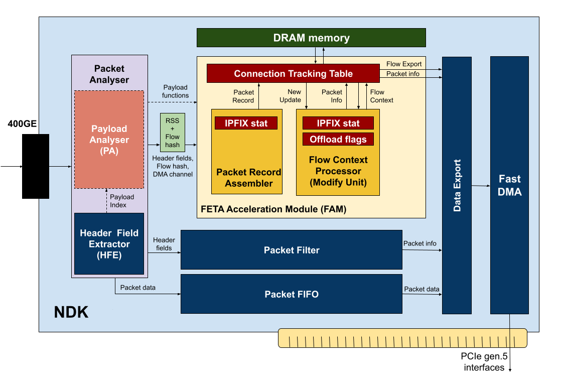 Figure 1: Hardware architecture of the FETA probe.
From the Packet Analyser unit, the results of header extraction and packet analysis are passed to two downstream units, which are the packet filter and the FETA Acceleration Module (FAM). Based on information from the headers and the payload, the packet filter determines whether the packet does not match any of the filtering rules. The result of filtering is the Packet Info data structure containing information about whether the packet should be sent to one of the output DMA queues, or whether the data is not interesting from the filtering point of view and should be discarded. The Packet Info structure is passed together with the packet identifier to the Data Export unit. The Data Export unit matches the packet identification with the data in the packet FIFO and with the result of packet processing in the FETA acceleration module (FAM) and, based on the result, sends the packet to the required DMA queues or discards the packet.
Processing in the FETA acceleration module begins with the preparation of a Packet Record, which represents the input packet. For each supported function, a data block is selected in the Packet Record Assembler (PRA) block. All selected blocks are then combined into one wide vector (Packet Record), which, together with the network flow identifier, is passed to the network flow table (CTT — Connection Tracking Table). The network flow identifier uniquely defines the network flow. A network flow is commonly defined using five: source and destination IP addresses, source and destination ports, and a protocol number. In the case of IPv6 addresses, the five take up quite a lot of bytes that must be stored for each flow. To save memory space, the exact network flow identifier is replaced by a 64-bit hash value calculated from the five.
The Network Flow Table (CTT) sequentially processes records extracted from packets (Packet Record) including the network flow identifier and maintains a context for each flow, which contains important information for all supported functions: (i) aggregation of IPFIX statistics, (ii) aggregation of parameters for classifiers, (iii) information for pre-filtering data in the Suricata IDS system (e.g. application of the Bypass rule). After receiving a Packet Record, the CTT searches for the network flow in memory, reads the associated context and passes it for processing to the Flow Context Processor (FCP) unit, which ensures the update of the record and the transfer of the resulting data back to the CTT. The CTT writes the updated context back to memory.
The FCP is responsible for initialization and update of the context. In order to make the processing modular and easily extensible, the context processing in the FCP is divided into separate units corresponding to the supported functions. Each unit then initializes and updates its part of the context. The export of records from the network flow table is controlled directly by the CTT based on an active timeout, inactive timeout or collision. However, the export of a record can also be forced based on data processing within the FCP.
In addition to initializing and updating the context, the task of FCP is also to provide information about further packet processing. Within the FCP, it is possible to request that a packet be forwarded to a specific DMA channel, that the packet be shortened, or that it be discarded. Each module within the FCP can indicate its interest in a packet with varying degrees of detail using the Packet Info data structure. The Packet Info structure contains a bit mask to indicate forwarding to a DMA queue and a number indicating truncation to a certain packet length. FCP aggregates information from the modules so that no data is lost for any application. DMA queues are indicated by a bit mask and aggregated by a logical OR operation, packet length (truncation) is aggregated by a maximum operation, discard is indicated by a zero DMA channel mask. If a packet is intended for more than one DMA queue, no hardware replication of the packet is performed. The packet is transferred over the